
Appearance
The interface, named
The rest of this documentation uses these names precisely, so it is worth a few minutes before the how-to guides.
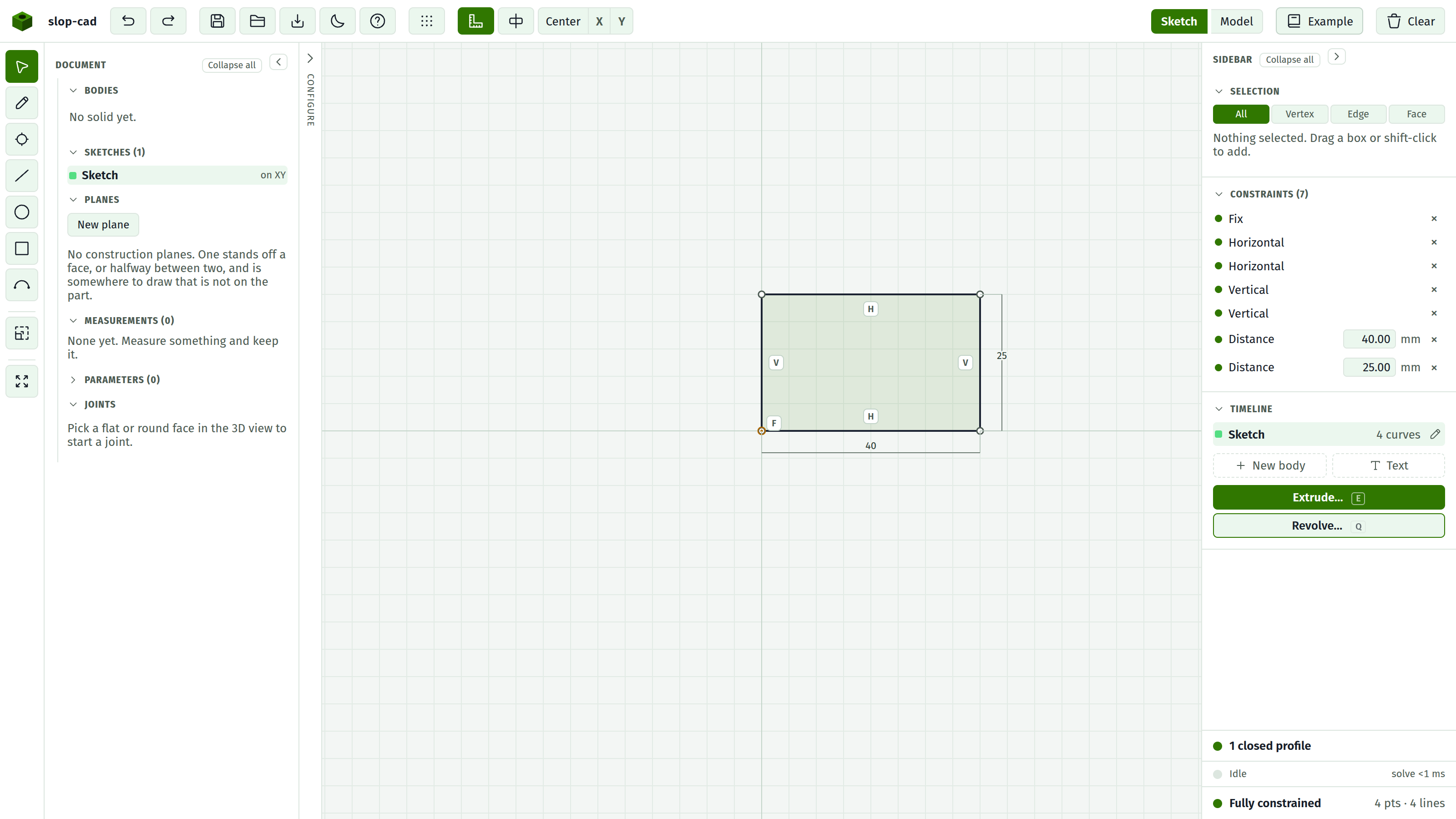
There are six regions: the top bar across the top, the tool strip down the far left, the document panel beside it, the canvas in the middle, the sidebar on the right, and the status foot pinned to the bottom of the sidebar.
The two panels differ on one thing. The document panel says what the document has. The sidebar says what you are doing to it. Both can be dragged wider by their inner edge, and either can be put away entirely, leaving a strip with the chevron that brings it back. On a screen narrow enough that the two would take most of it, the document panel starts put away.
A seventh region appears on demand: the Configure panel, a second drawer beside the document panel holding the parameters a creator chose to expose as controls. Its collapsed strip says Configure.
The top bar

Left to right: the name, then undo and redo, then Save, Open, Import, a half-moon that swaps the light theme for the dark one, and a question mark that opens this documentation in a new tab. The theme starts at whichever your machine asks for; press the half-moon once and the choice is yours from then on.
After those comes a group that appears only in sketch mode: grid snap, the constraint glyph switch, add midpoint, and the Center / X / Y trio that moves the drawing onto the sketch origin.
On the right: the Sketch / Model view toggle, then Example and Clear.
The Model button stays disabled until a solid exists. Its tooltip says so.
Full detail: saving, opening and clearing.
The tool strip

Seven drawing tools and a view control, top to bottom:
| Icon | Tool | Key |
|---|---|---|
| Cursor | Select | V |
| Pencil | Pencil chain | D |
| Crosshair | Point | P |
| Diagonal | Line | L |
| Circle | Circle | C |
| Square | Rectangle | R |
| Arc | Arc | A |
| Expand | Recenter the view | F |
The last one is not a drawing tool. It frames the drawing in the viewport without moving any geometry.
The shortcuts work wherever you are in the app. The one exception is a field you are typing into, which keeps its own keystrokes.
Full detail: the tools.
The document panel
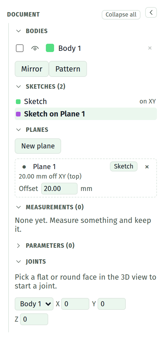
Six groups under one heading, folding together. Collapse all folds the whole tree at once; the chevron beside it puts the panel away, leaving a strip with the chevron that brings it back.
Nothing here configures a command you have not run yet. What lives here is the settings of things that already exist: a body's colour, a plane's distance, a joint's angle, a parameter's value.
Full detail: the document tree.
Bodies
One row per solid the document builds: a tick box, an eye that hides it, a swatch that paints it, its name (click to rename), and a × that deletes it along with its sketches.
The list folds into groups. Tick some bodies and a strip appears offering to move them into a new group or an existing one. A group has a caret that folds it shut, one eye that switches everything in it at once, and a name. A file holding more than one part arrives already grouped. Grouping changes nothing about what builds.
Below the list, the control that booleans two bodies together: join them, cut one with the other, or keep only what they share. The body you combine with is consumed. Each combine is then listed in the order it is applied, and dropping one puts the consumed body back. The picker only appears once there is more than one body to combine.
Full detail: Bodies.
Sketches
One row per sketch, saying what it stands on. Click a row to enter that sketch. This is what the document HAS; the timeline further down says the order it was built in.
Planes
The construction planes: datums with no material in them, that a sketch can be drawn on. New plane builds one, either a typed distance off a flat face (or a world plane) or halfway between two parallel ones.
Each row can be renamed, shown or hidden in the model view, sketched on, and deleted. An offset plane carries the one number it has, and that number can be driven by a parameter. A plane is derived on every rebuild, so it rides a change in whatever it is measured from and carries every sketch on it along.
Full detail: construction planes.
Measurements
Measurements kept on the model, each re-taken off every new solid rather than remembered as a number. One that no longer has anything to measure between says so instead of showing a stale figure.
Full detail: measuring in 3D.
Parameters
The document's named values: a name, an expression, and what it came to. Once one exists, any dimension, extrude distance or blend size can be driven by it, and moving the value moves everything that names it.
Starts collapsed and empty. New parameter adds a row.
Full detail: parameters.
Joints
What holds one body against another. Click a face, press Grip, click a face on another body, press Joint: the second body is brought to meet the first and follows it from then on. Each joint carries an offset along the axis the two faces share and an angle about it.
Underneath, a body picker and X, Y and Z fields: that is how the body at the head of a chain is pushed, and everything jointed to it comes along.
Full detail: joints.
The canvas
The 2D sketcher, or the 3D model view, depending on the Sketch / Model toggle.
In sketch mode it draws your geometry, the dimension annotations, a grid whose spacing follows the zoom, and a shaded fill over any closed profile. In model mode it draws the solid, a ground grid, and an axis triad coloured red for X, green for Y, and blue for Z.
Overlays that appear here when relevant:
- A hint strip along the bottom while the Pencil tool is active.
- A floating constraint bar at the top whenever a selection has constraints available.
- An empty-state card in the middle of a blank document.
- A navigation cube at the top right in model mode, which turns with the camera and aims it when clicked.
- View buttons just below it: Top, Front, Right, Iso, and X-ray.
- Reference tools at the top right in sketch mode, when the current sketch sits on a face of the solid.
The sidebar
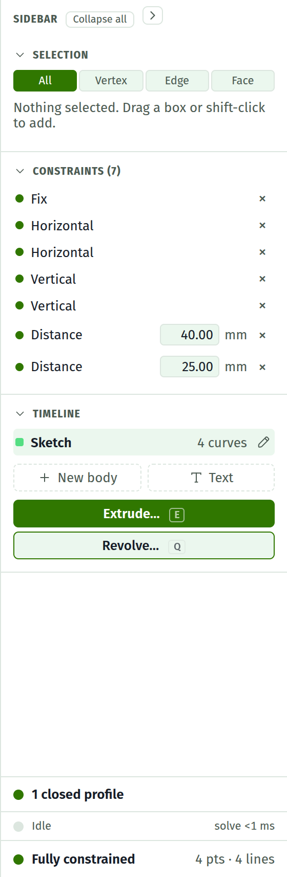
Two regions, top to bottom.
What is picked, and what is holding the sketch you are in: Selection, Constraints, and the references this sketch has traced off the model. All of it changes when the active sketch does.
Timeline: the order it was all built in.
Collapse all in its head folds every section at once, and the chevron beside that puts the whole panel away. Individual headings collapse when you click them, and what you leave open is remembered. Drag the panel's left edge to make it wider.
Settings for a command you have not run yet are in neither. They are in a floating dialog over the viewport, next to the thing the command is about.
Selection
What is currently picked, and what you can do to it.
At the top, the four select modes: All, Vertex, Edge, Face, on keys 1 through 4. They narrow what a click or a drag box is allowed to grab, in both the 2D and 3D views.
Below that, a description of the selection, and then a row of buttons, one per constraint that applies to it. When a single point is selected you also get editable X and Y fields. When a face of the solid is picked, this is where Sketch on face, Text on face and Blend rim appear; each opens its own dialog over the viewport.
Full detail: the Selection section.
Constraints
The docket: one row per constraint in the current sketch.
Each row carries a coloured dot for its state, its name, an editable value if it is a dimension, and a delete button. Clicking a row highlights the geometry it names. Selecting geometry tints the rows that mention it.
The four dot colours:
| State | Meaning | |
|---|---|---|
| Solved | Satisfied, and it is doing work | |
| Redundant | Satisfied, but something else already forced it | |
| Conflicting | It cannot be satisfied alongside the others | |
| Unsolved | The solver has not reached it |
Full detail: the constraint docket.
Timeline
The ordered list of what the document is made of: each sketch, its extrude if it has one, and any blends, each with a coloured swatch and a delete button.
Below the list: New body, which starts a solid of its own, the volume and triangle count of what is currently shown, the STL and OBJ export buttons, and the controls for extruding whichever sketch is currently active.
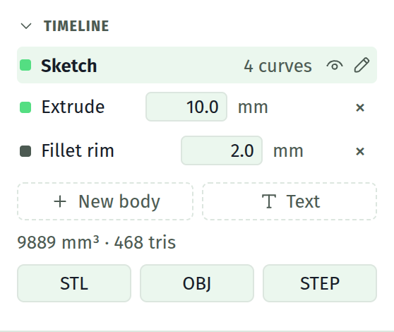
Full detail: the timeline.
The status foot
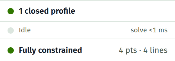
Pinned below the sidebar so it is always visible, whatever you have scrolled to. Three rows, top to bottom.
Profiles. How many closed profiles the sketch has, or a warning that a profile is open or the geometry branches. Only closed profiles can be extruded.
Activity. Whether the kernel is rebuilding and which stage it is in, or when idle, how long the last solve and the last rebuild took. The figures turn amber when they are slow enough to notice, which tells you which half of the work is costing time.
State. Fully constrained, a count of remaining degrees of freedom, or unsolved, with the entity counts on the right. This row is a button. Clicking it highlights the geometry that still has freedom and jumps you to the docket.
Full detail: the status foot.
Next
Build your first part if you have not, or go straight to the tutorials.