
Appearance
Timeline
The bottom section of the sidebar: an ordered list of everything the document is made of. It says the ORDER things were built in; the document tree above it says what there is.
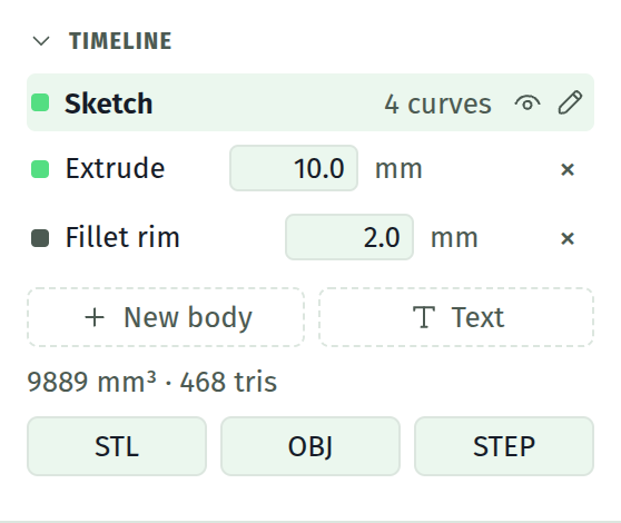
Order is build order. Each row is folded into the solid in the sequence shown.
Sketch rows
| Element | What it does |
|---|---|
| Colour swatch | Clicking it rerolls that part's colour in the 3D view. It does not select the row |
| Label | Sketch for the first, Body 2, Body 3 for later base sketches, or Sketch on top face / Sketch on side face / Sketch on face #N for one sitting on the solid |
| Curve count | Shown on the active row |
| Eye icon | Make this sketch active and switch to the model view |
| Pencil icon | Make this sketch active and switch to the sketch view |
| × | Remove this sketch and its feature |
Clicking anywhere else on the row makes that sketch active for editing.
The first sketch cannot be deleted; it has no ×. Deleting any other cascades: any sketch sitting on a face of the one you remove goes too, along with any blend that named one of their faces.
WARNING
Switching the active sketch clears undo and redo. Finish what you are doing before you click another row. See undo.
A stale reference
A row whose label turns amber, with a second amber line beneath it, has lost the face it was drawn on. The message says which of three things happened:
- the face it sits on is gone
- the face it sits on is no longer flat
- the feature it sits on has no solid
The sketch keeps building on the last plane it knew, so the model does not silently move.
To repair it, pick a face in the 3D view and press the link button on the amber row. The sketch moves to that face with its geometry and constraints intact. See face references.
Feature rows
Sit beneath their sketch. A pushed feature is labelled Extrude or Cut, with a midplane note when symmetric; a turned one is Revolve or Cut revolve, noting which axis it turns about.
A live size field, accepting arithmetic: millimetres along the normal for a push, degrees about the axis for a turn. Change it and the solid rebuilds. The rewind icon rolls the build back to this feature. The × removes the feature; removing the last one drops you back to sketch mode with no solid.
Blend rows
Labelled Chamfer or Fillet, suffixed rim, chain, or loop to say how far the blend reaches. A plain edge blend has no suffix.
A live size field, a rewind icon and a ×, the same as an extrude.
Blends are features of the body, not of any sketch, so they always apply after every extrude regardless of where they sit in the list. An edge does not exist until both the faces meeting at it do. See blends.
The rollback marker
The rewind icon on any extrude or blend row builds the timeline up to that feature and no further.
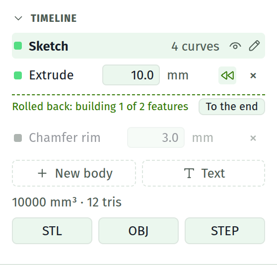
A dashed line appears where the marker sits, reading Rolled back: building N of M features, and every row below it dims. The dimmed features are still in the document with their fields intact; they are absent from the solid.
| To do this | Press |
|---|---|
| Roll back to a feature | The rewind icon on its row |
| Come back to the end | To the end on the marker line, or the rewind icon it is standing at |
The marker counts every extrude in order, then every blend, which is the order the build folds them in.
What follows the marker:
- The solid is built as of that feature.
- The Bodies list shows only the bodies that far builds, and the volume is theirs.
- A face pick can only reach faces that exist at that point.
- The sketch you are editing is unaffected. Any sketch can be made active and edited wherever the marker stands.
The marker is not saved with the document, and it is not an undo step. It says what you are looking at, the same as which sketch is active.
TIP
Making a new feature while the marker is rolled back returns it to the end. A new feature lands at the end of the list, so building without it would look like the feature had failed.
Below the list
New body. Appends another base sketch on the world XY plane and makes it active. It is labelled Body 2, Body 3, and so on. Read what a body is before assuming this gives you separate solids: it does not.
Stats. N mm³ · M tris, once a solid exists. The volume is of the finished solid, so it is a quick check that a cut removed what you expected.
Export. STL and OBJ buttons. See export formats.
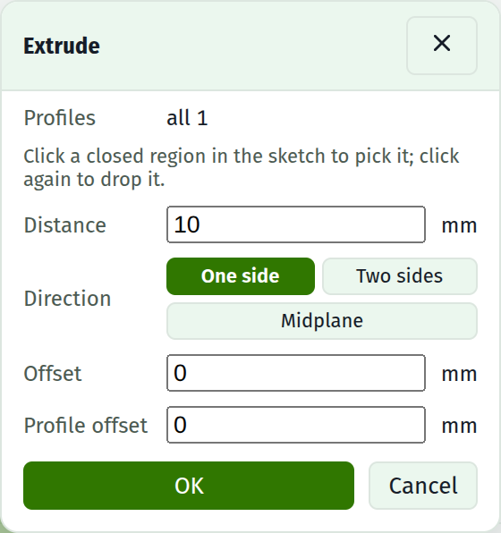
The solid controls
Shown when the active sketch has no feature yet.
| Control | Notes |
|---|---|
| Extrude… | Opens the extrude dialog over the drawing. E does the same |
| Revolve… | Opens the revolve dialog instead, which turns the profile about an axis rather than pushing it. Q does the same |
Each dialog holds its own numbers, the operation and the profile pick. Both buttons are disabled until there is at least one closed profile, with Close a profile to build a solid from it. under them.
Errors
Rebuild failed: in red means the whole rebuild failed. The last solid that built stays on screen so you are not left with an empty viewport, and the model view says so over the top of it.
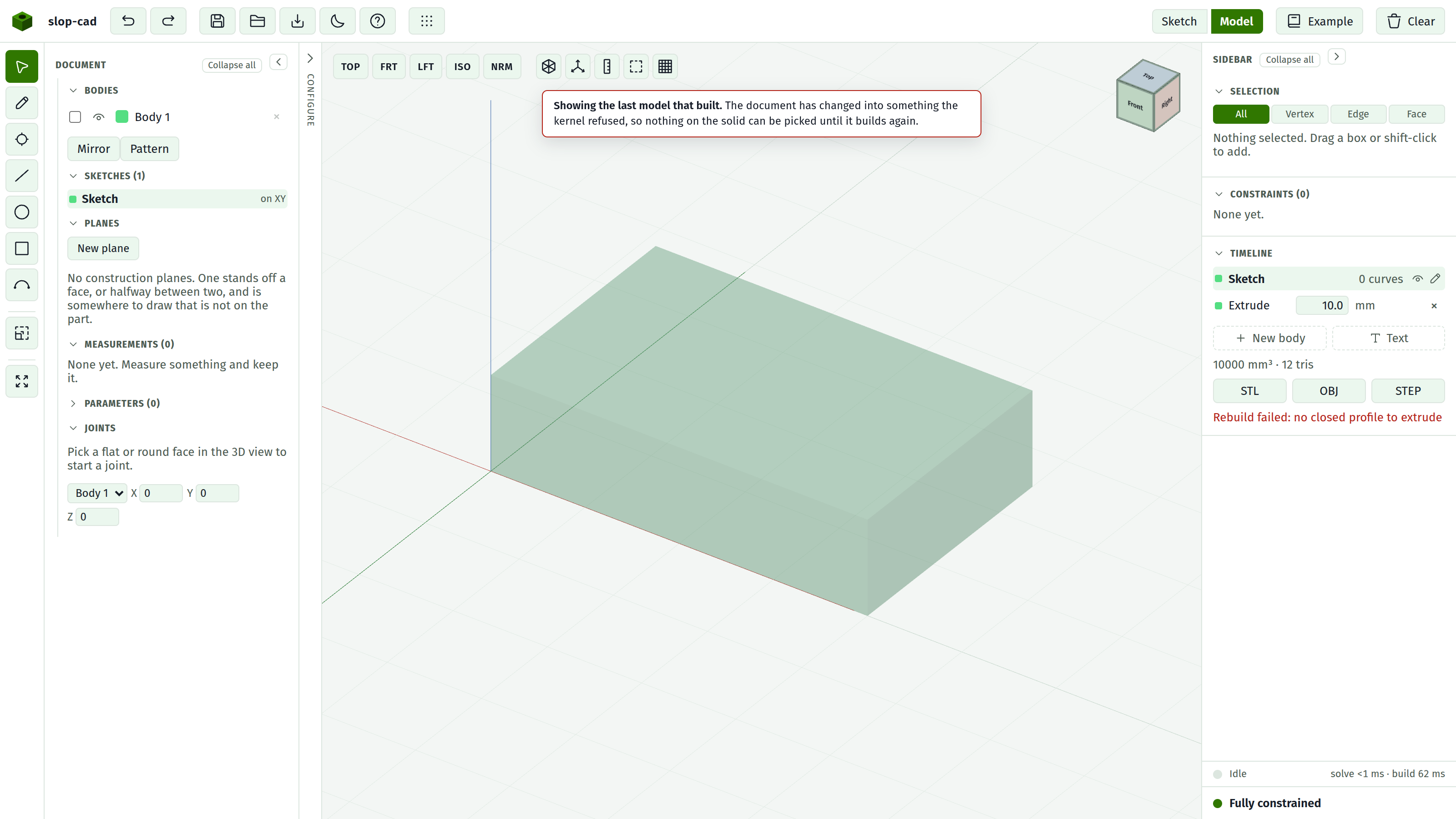
That solid is not the part any more, so while the message is up it takes no picks: no face, no edge, no corner, and nothing already picked stays picked. A blend aimed at it would be stored against a face that is not coming back. Construction planes are the exception, since a plane is something the document holds rather than something the kernel built, and starting a sketch on one is a way out.
Body build: in amber means the boolean step failed but the individual pieces still drew. You are looking at the parts rather than the finished solid. Common causes are a holed cut that reaches the far side of the body, or a new base body overlapping existing material.