
Appearance
Import a mesh
The import icon in the top bar opens Import. Its From a mesh file section takes an STL or an OBJ, which are the files a printer, a scanner or a downloaded model come as.
One read of the file affords two different things:
- Add whole as body stands the mesh in the model, to build around and measure against.
- Trace this region takes one flat face of it as a sketch to draw against.
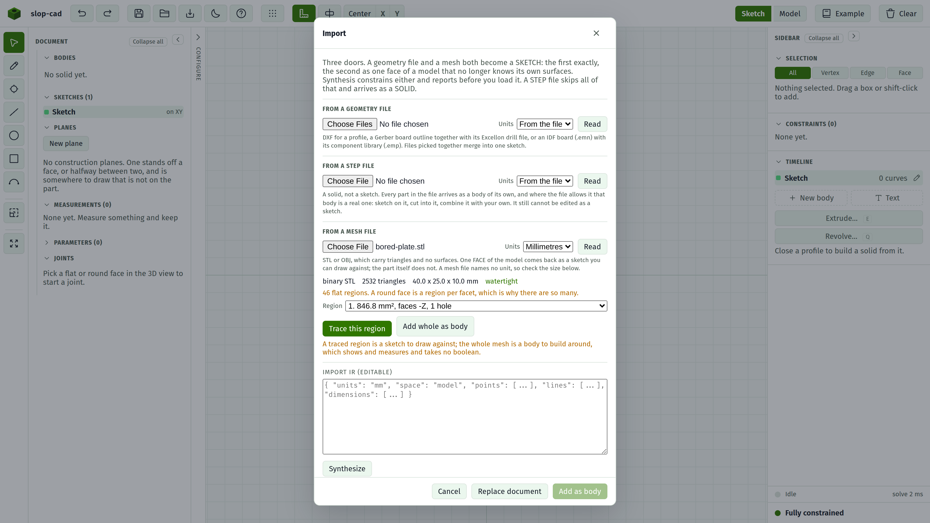
- Pick the file.
- Set Units. A mesh file states none, so this is your decision. See below.
- Press Read. Nothing is added yet.
- Check the size.
- Either press Add whole as body, or pick a Region and press Trace this region followed by Add as body at the foot.
The mesh as a body
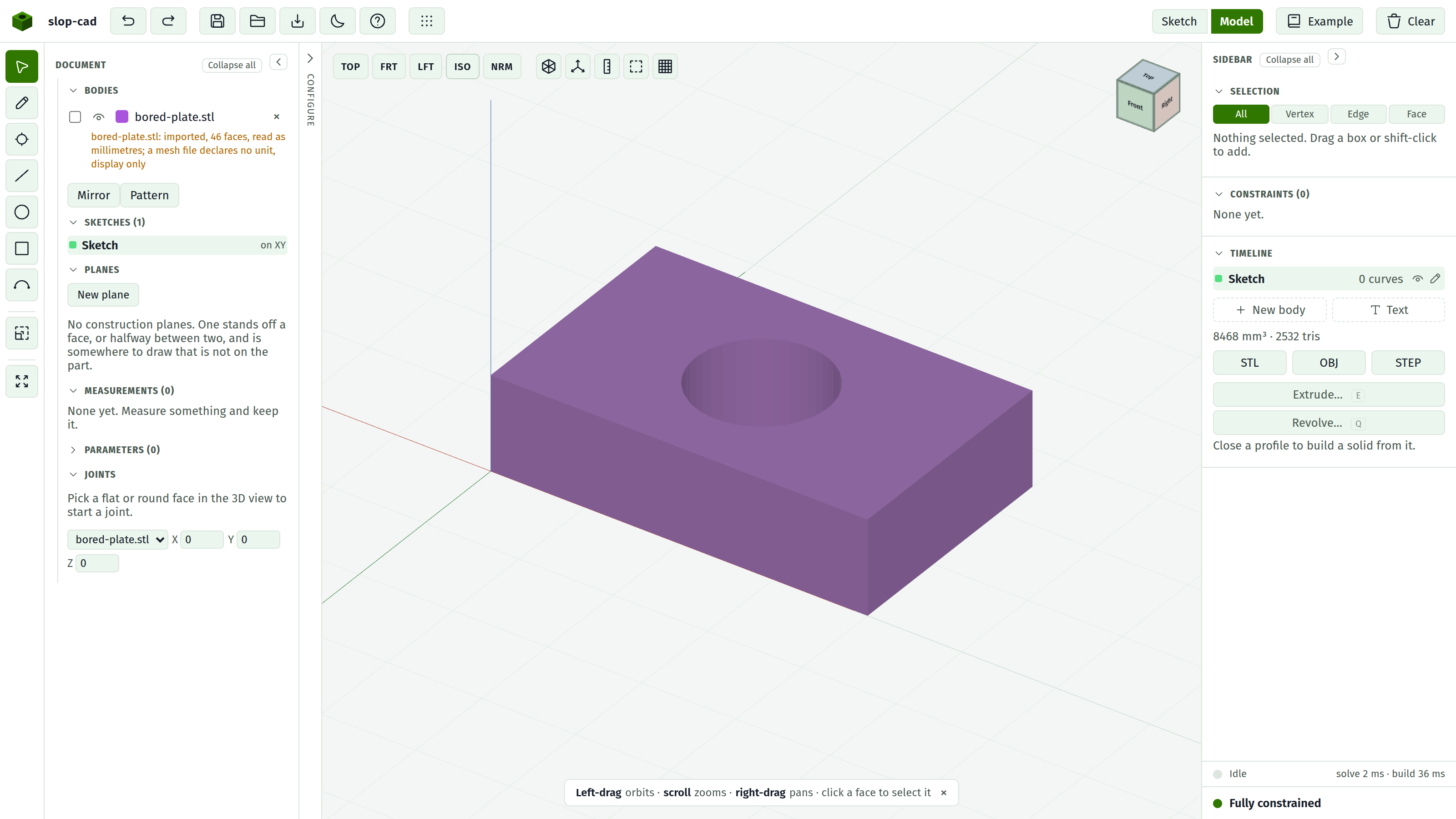
The whole file stands in the model as one body, with a row in the Bodies list carrying an eye, a colour, a name and a delete like any other. It contributes to the displayed volume and goes into an exported mesh.
It is a picture: it shows and it measures, and no boolean can be aimed at it. That is the same state a STEP part is in when its surface would not convert, and it is where every mesh stays, because triangles bound no volume the modeller can name.
A sketch can be started on any flat face of it. Pick the face in the model view and press Sketch on face. The facets are grouped into the planes they fell into, so the top of a plate is one face to land on rather than a thousand loose triangles. What you build there stands as a body of its own beside the mesh, since there is nothing to join to.
One body, always. A mesh file says nothing about where one part ends and the next begins, so a file holding six loose pieces arrives as one body holding six loose pieces.
Why a face and not the part
A mesh is triangles and nothing else. The part it was written from had faces and surfaces and a history, and all of that was thrown away when the file was made: a bore in an STL is not a hole of a stated size, it is forty flat facets that happen to stand in a ring.
So there is no honest way to hand you back the part as something you can edit. What there is is the flat regions, which are exactly the places a sketch can stand, and their outlines. That is enough to measure against, to trace a mating part off, and to build your own model around a shape somebody sent you.
For a file that still knows what it is, use STEP. That one arrives as a solid you can cut into.
The report
| Line | Meaning |
|---|---|
| binary STL, ASCII STL, OBJ | How the file turned out to be written, read from its contents |
| N triangles | What it holds |
| X x Y x Z mm | How big it is once the unit is applied. The check that the unit is right |
| watertight | The surface closes |
| not watertight | It does not. Regions still trace correctly; it is printing the file that would fail |
| N flat regions | How many distinct planes its facets fell into |
A model with any roundness in it reports far more regions than it has faces, because every facet of a bore lies in a plane of its own. They are listed largest first, so the faces worth drawing on are at the top and the litter is at the bottom.
Picking a region
The Region list names each one by its area, which way it faces, and what is cut out of it: 846.8 mm², faces +Z, 1 hole.
Area is what to go by. The face of a plate is hundreds of square millimetres; a facet of the bore through it is a few.
Both faces of a plate are the same size and both appear. Either traces correctly; they are mirror images of each other, so pick the one you mean to look at.
What a traced region gives you
The region's outline and every hole in it, in the plane the face lies in, with the sketch origin at the point of that plane nearest the model's own origin.
Straight edges come back as single lines, however many triangles the file split them into.
A round hole comes back as a circle. The facets around a bore sit exactly on the circle they were cut from, so the circle can be recovered from them, and it is: a forty-facet ring becomes one circle of the right radius. Fillets and rounded corners come back the same way, as arcs.
A coarse mesh comes back as the polygon it is. Below about sixteen facets to a full turn, a ring of facets is no longer evidence of a circle, and a hexagonal hole is a hexagon rather than a badly drawn circle. It is read as what it says: six sides.
Nothing is dimensioned
The sketch arrives with no driving dimensions at all, and this is deliberate.
The numbers in a mesh are what the file happens to say, one tessellation removed from what the part was designed to be. A bore that measures 6.998 mm was a 7 mm bore, and writing 6.998 into your sketch as though it were a decision would be a lie with three decimal places on it.
So the geometry is placed and left free. Add the dimensions you mean to hold, and the status foot tells you what is still loose. See apply constraints.
Units
Nothing in an STL or an OBJ says what a unit is worth. Millimetres is the default and is right most of the time; a file exported from an inch-native tool wants Inches.
The size line is how you tell: a bracket that reads 1.6 x 1.0 x 0.4 mm is an inch file read as millimetres. Change the unit and press Read again.
What you cannot do with it
It cannot be cut into. To carve an imported mesh you would need it as a solid, and turning triangles back into a solid is not something this does. Neither a feature nor a combine can be aimed at one.
It has no timeline row and nothing to edit. The file is the shape.
Only one region at a time. Read the file again to trace a second face.
The volume is the file's own. A bore reaches the model as the chords its facets are, so a bored part measures a little heavy. That is the mesh rather than the reading.
See also
- Import a solid, for a STEP file that arrives whole
- Import a geometry file, for DXF and Gerber
- The import dialog, for every control
- Export a mesh, for the other direction