
Appearance
Import a solid
The import icon in the top bar opens Import. Its From a STEP file section is the one door that does not produce a sketch: what arrives is a finished solid, a stock part or a vendor component, standing in the model for you to build around and measure against.
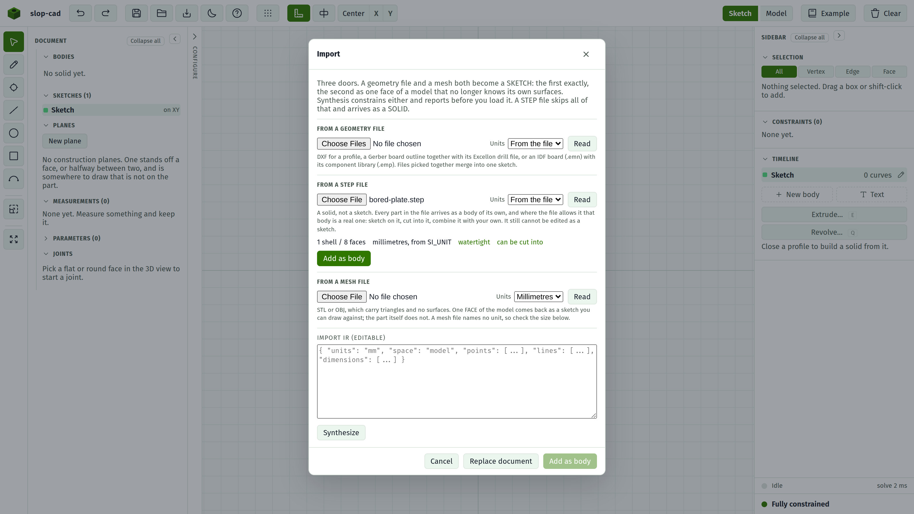
- Pick the file.
- Leave Units on From the file unless the size comes out wrong. See below.
- Press Read. Nothing is added yet.
- Read the report.
- Press Add as body.
The report
Reading happens before anything is committed, because a foreign solid is the one input here that can fail for reasons you cannot see from the file picker.
| Line | Meaning |
|---|---|
| N shells / N faces | What the file turned out to hold. A part is usually one shell; an assembly is several |
| N shells, N placed | An assembly that uses a part more than once. See below |
| The unit sentence | What the file said it was drawn in, and how many millimetres that is |
| watertight | The surface closed. Its volume is exact and it will print |
| not watertight | The surface has gaps. See below |
| can be cut into | The shape came across as real geometry, so a boolean can be aimed at it |
| display only | It shows and measures, but nothing can cut into it. See below |
| N of N can be cut into | An assembly where only some parts came across as solids |
| Refusals | Any shell that could not be read or used, and why |
What an imported solid is, and is not
It is a body, one per part in the file. Each appears in the Bodies list with an eye, a colour, a name and a delete, exactly like a body you built. Each contributes to the displayed volume and goes into an exported mesh.
It is not a feature, so it has no row in the Timeline and nothing about it can be edited. There is no way to change its shape, because the file is the shape.
A boolean can be aimed at it, when the report says can be cut into. It is a target or a tool in the Bodies list's combine picker like any other body, so the way to carve a stock part is to draw the shape you want removed as its own body and cut that out of the import.
A sketch can be started on any flat face of it. Pick the face and press Sketch on face, the same gesture as on a part you built, then draw the pocket and extrude it as a cut. The face is held by the PLANE it lies in rather than by a feature, since no feature made it, and that survives the face being cut into.
When a part is display only
A part is in this state when its surface does not close, so there is no solid to cut into. It still shows, measures and exports.
This is decided per part, so an assembly is usually mostly usable: the report says 43 of 45 can be cut into when two parts of a board came across as surfaces and the rest as solids. The two that did not are the ones you cannot aim a boolean at.
When it is not watertight
Foreign solids often are not. What that means is worth understanding, and it is not usually worth worrying about.
Two faces meeting along an edge can be broken into differently sized straight pieces by each side, and the sliver of a gap that leaves is far too small to see. The part still displays correctly and still measures correctly in every direction you can point at. What it does not do is close, so:
- its volume is an estimate, not a figure to quote;
- an exported mesh will not print as it stands, and needs repairing first.
Neither affects using it as something to build against, which is the job an import is there to do.
When the size is wrong
A STEP file states its units, and the report says which it found. Most are in millimetres; some are in metres, and a part in metres read as millimetres arrives a thousand times too small.
If the size is out by a round factor, set Units to what the file meant and press Read again.
What an assembly does
An assembly is read whole. Each part is put where the file says it belongs, so a populated circuit board arrives with its components standing on the board rather than stacked inside it.
Every part becomes a body of its own. A board with forty-five components gives you forty-five rows in the Bodies list, each with its own eye, colour, name and delete. Hide one, paint one, cut into one, or delete one, and the rest are untouched.
They arrive folded into a group named after the file, so the list stays one row until you open it, and the group's eye switches the whole assembly off at once. The × on the group breaks the folding up without touching a single body. See the bodies list.
They arrive named as the file names them, so the rows read C6, R10, Board:1 rather than Body 12. A file that names nothing numbers them Part 1, Part 2 instead. Renaming one yourself overrides both.
A part used more than once is drawn once per use, and each use is its own body. The report counts the two separately, because they are different numbers: 3 shells, 12 placed means the file describes three distinct parts and puts them down twelve times between them, giving twelve bodies.
Assembly structure beyond the placements and the names is not read: no hierarchy, no constraints. Nothing holds the parts together, so moving one does not move its neighbours.
What is not read
Colours and materials.
Wireframe and surface-only files have no shells and are refused, with a message saying so.
See also
- The import dialog, for every control
- Import a geometry file, for the 2D door
- Import a mesh, for an STL or OBJ, which arrives as a picture
- The bodies list, for groups and per-body visibility
- Bodies, for what a body is here