
Appearance
Import dialog
Turning something that is not a sketch into a constrained sketch. Opened with the import icon in the top bar, labelled Import.
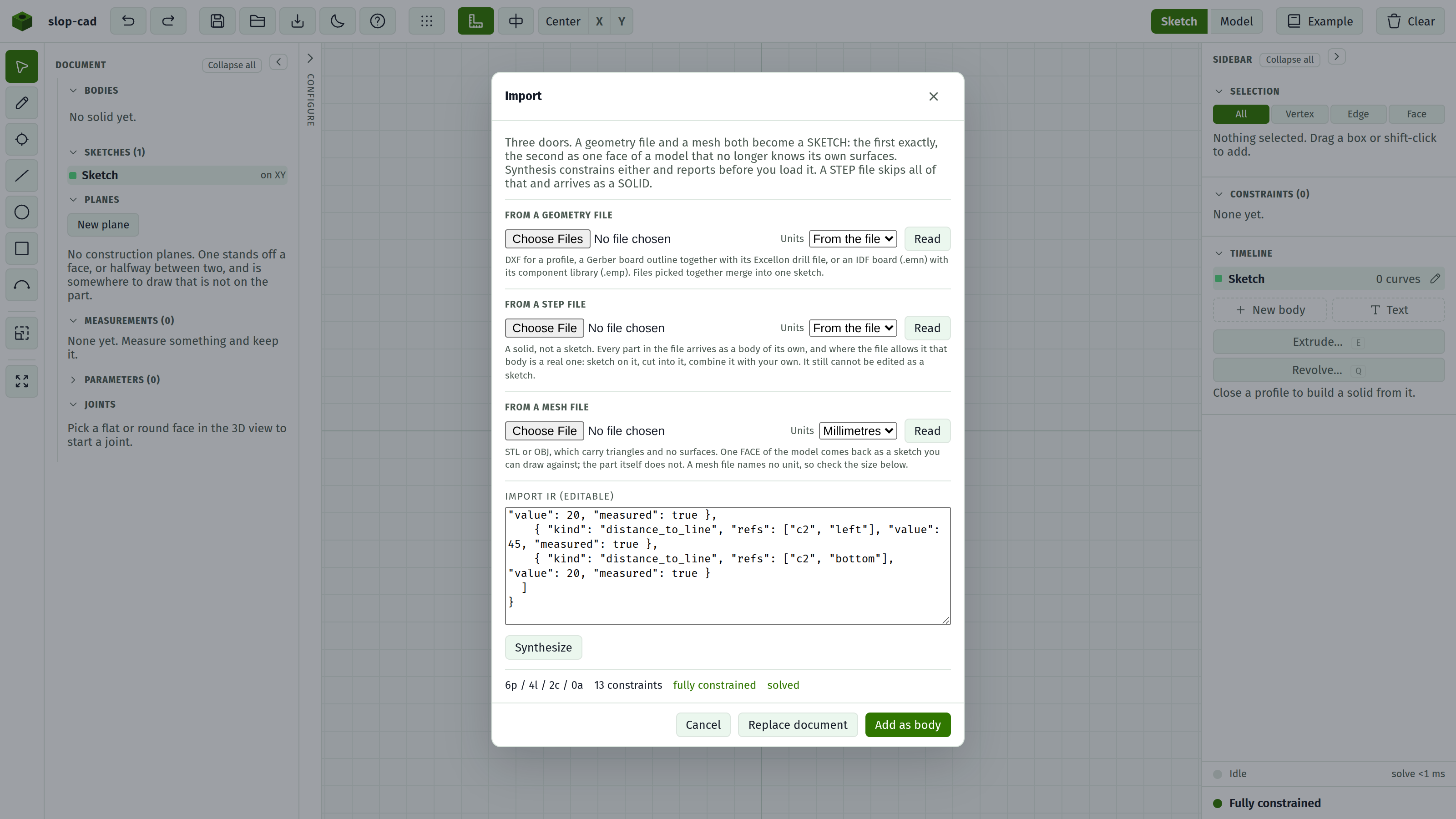
Close it with Cancel, the ×, Esc, or a click on the backdrop.
Three doors lead in, and they do not all lead to the same place.
A geometry file is read exactly, and a mesh file gives up one flat face of a model that no longer knows its own surfaces. Both produce the same description, in the text area in the middle, and everything after that is shared: synthesise a constrained sketch from the description, then load it.
A STEP file skips all of that. It is already a solid, so it arrives as a body rather than as a sketch, and has its own Add button in place of the ones in the footer.
Door 1: a geometry file
| Control | Notes |
|---|---|
| File picker | DXF, Gerber (RS-274X), Excellon, or IDF (.emn with its .emp). Takes several files at once |
| Units | From the file, unless the file declares none. Millimetres and Inches override it |
| Read | Reads the files and synthesises in one step. There is no separate Synthesize press |
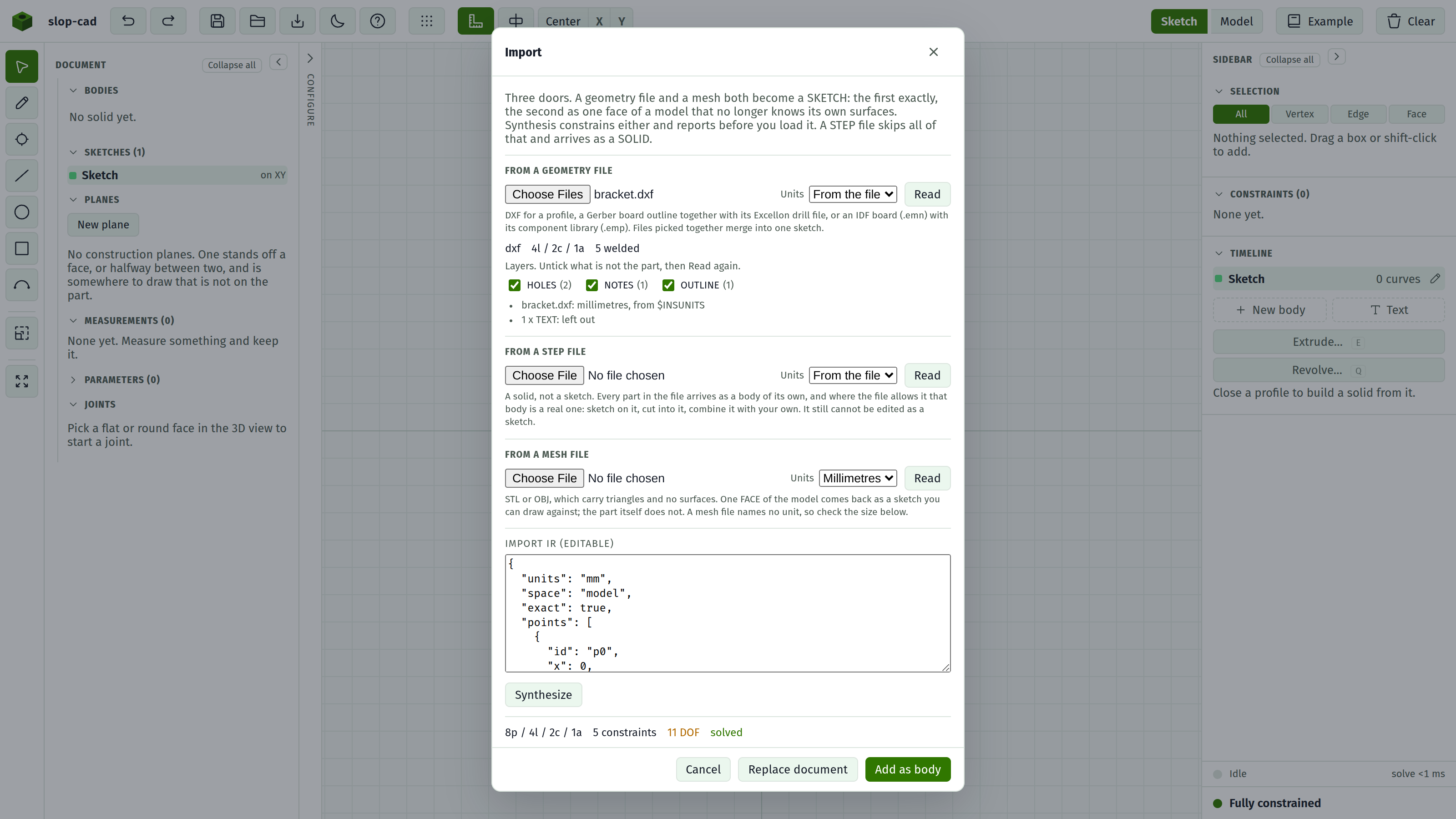
Picking more than one file is how a board arrives: a Gerber outline layer and its Excellon drill file are read into one sketch, outline plus holes, and an IDF board file with its component library reads the same way. Several DXFs merge too. Which reader handles which file is decided by what is inside it, and not by the extension.
The report that appears names each format, counts what was read, and lists every assumption it had to make. Failures show as Could not read the file: with the reason.
| Format | Read | Left out |
|---|---|---|
| DXF | Lines, polylines with their rounded corners, circles, arcs, points, blocks stamped where they are placed, dimensions as driving constraints | Text, hatching, ellipses |
| Gerber | Traces and arcs, along their centre line. Round pads become circles | Other pad shapes, polarity changes |
| Excellon | Every hole, at its tool's size | Routed slots |
| IDF | Board outline with its cutouts, drilled holes, and component outlines stood where the board places them | Keepouts, routing areas, pads, copper, component heights |
Everything left out is counted in the report instead of being dropped in silence.
A welded count in the report is how many endpoints turned out to be a corner already placed. A closed outline welds one per corner; a shape that should be closed and welds nothing has gaps in the file.
A driving count is how many of the DXF's own dimensions became constraints you can edit. A spline note says how many curves were read as straight segments, which is the one thing here that is approximated.
The report also lists every layer the drawing put something on, as tickboxes. A sheet border and a title block are geometry and nothing in the file says they are not the part, so untick what is not and press Read again. An IDF board's sections read as its layers, so the same pass keeps the blank and drops the population.
Full walk-through: import a geometry file.
Door 2: a STEP file
| Control | Notes |
|---|---|
| File picker | One .step or .stp file |
| Units | From the file, unless the size comes out wrong by a round factor |
| Read | Reads and describes it. Adds nothing yet |
| Add as body | Appears with the report. Adds the solid to the document |
Reading is separate from adding because a foreign solid is the one input here that can fail for reasons invisible from the file picker, and the refusal is worth having before the document changes.
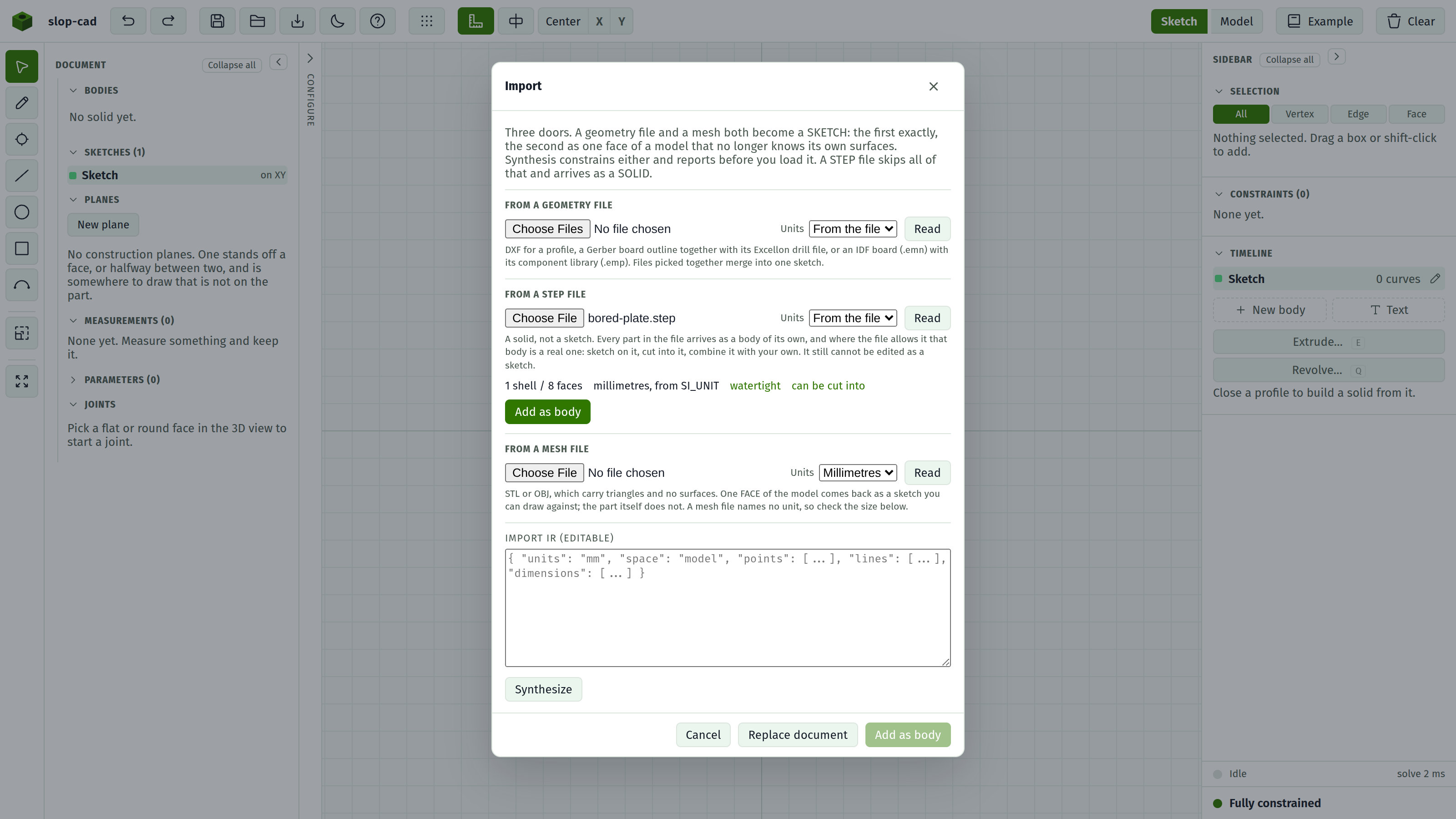
The report gives shell and face counts, the unit the file declared, whether the surface came out watertight, and whether the solid can be cut into. An assembly also says how many times its parts were placed, since one part definition used repeatedly is one shell in the file and several bodies on screen.
Every part in the file becomes a body of its own, named as the file names it, so a board of forty-five components gives forty-five rows in the Bodies list. Each is hidden, painted, renamed, cut into or deleted on its own. An imported body is not a feature: it has no Timeline row and nothing about it can be edited. Where a part reads can be cut into it takes a boolean like any other body, and a sketch can be started on any flat face of it.
Full walk-through: import a solid.
Door 3: a mesh file
| Control | Notes |
|---|---|
| File picker | One .stl or .obj. Binary and text STL are both read, told apart by the file's own length instead of its header |
| Units | Millimetres or Inches. A mesh file states no unit, so this is a decision rather than a reading |
| Read | Reads the file and lists the flat regions it is made of. Adds nothing yet |
| Region | Which flat region becomes the sketch, largest first |
| Trace this region | Turns that region's outline into a description, and synthesises it |
| Add whole as body | Stands the whole mesh in the model instead, as a body |
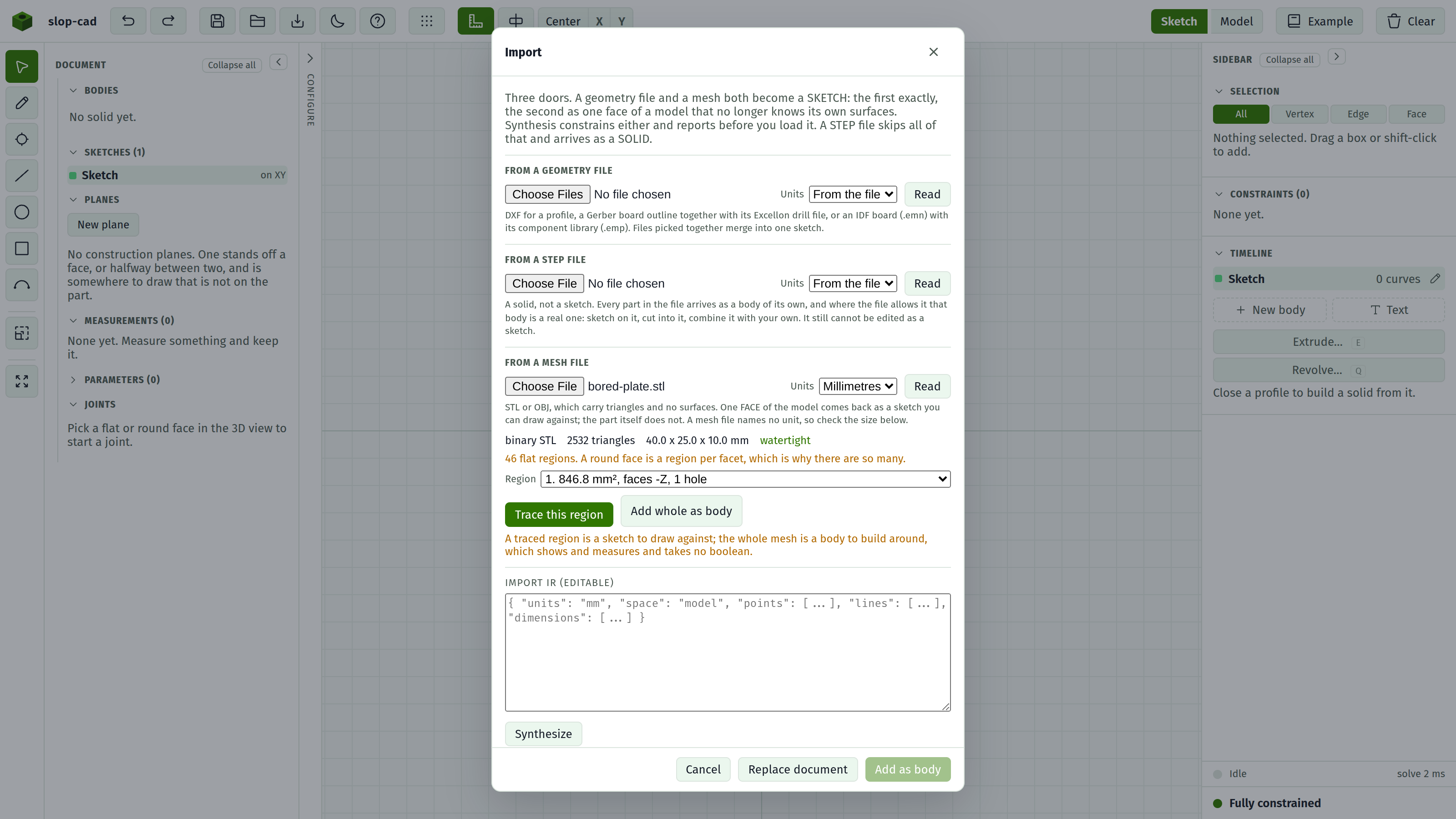
A mesh has thrown its surfaces away, so this door offers two things and neither is the part. Trace this region returns a FACE: the region's outline and its holes, in the plane the face lies in, as a sketch. Add whole as body returns the triangles: a body that shows, measures and hosts a sketch on any flat face, and that no boolean can be aimed at. A mesh is a picture wherever it goes here.
The report names the format, the triangle count, the model's size in millimetres, whether the surface closed, and how many distinct planes the facets fell into. That last number runs into the hundreds on anything round, because every facet of a bore lies in a plane of its own; the list is sorted by area, so the faces worth drawing on are at the top.
Straight edges come back as single lines and a ring of facets comes back as the circle it was cut from. Below about sixteen facets to a turn the ring is read as the polygon it has become, which is also what keeps a hexagonal hole hexagonal.
Nothing traced is dimensioned. The numbers in a mesh are a tessellation away from the ones the part was designed to, so the geometry is placed and left free for you to dimension.
Full walk-through: import a mesh.
The description
A large editable text area holding the description a reader produced, in a simple documented shape. You can type or paste one directly, which is a door of its own: anything that can write this shape can drive the importer.
The shape:
| Field | |
|---|---|
units | mm, cm, or inch |
space | model for real coordinates, pixel for image coordinates |
scale | Millimetres per pixel. Only for pixel space |
points | {id, x, y} |
lines | {id, a, b}, naming two point ids |
circles | {id, center, r} |
arcs | {id, center, start, end, ccw} |
dimensions | {kind, refs, value} where kind is distance, distance_to_line, diameter, radius, or angle |
Synthesize builds a sketch from it. Errors show as Synthesis failed:.
Pixel-space input with neither a scale nor a distance callout cannot be sized, and says so: nothing establishes how many millimetres a pixel is worth.
What synthesis adds
It does more than transcribe. It infers the constraints a drawing implies:
- Lines within 2 degrees of an axis become Horizontal or Vertical.
- Points within 0.4 mm of each other are merged as Coincident.
- Circles with no dimension of their own, whose radii agree within 2%, are made Equal.
- The lower-left point is Fixed, so the sketch has an anchor.
- Every measured callout becomes a driving dimension, with units converted.
If the result will not solve, it makes up to six repair passes, each dropping the single most contradictory dimension. This is aimed at a misread number rather than at a drawing that cannot be solved at all.
A description read from a file gets almost none of this. The tolerances above are what make a guess usable, and a file is not a guess. Only two of the rules survive: a line the file puts on an axis becomes Horizontal or Vertical, and the lower-left point is Fixed. Nothing is merged on proximity, since the reader has already joined the endpoints that met, and nothing is made Equal, because two holes a file says differ by a hundredth differ by a hundredth.
The report
After synthesis, before you load anything.
| Line | Meaning |
|---|---|
| Entity counts | Points, lines, circles, arcs |
| Constraint count | How many were inferred |
| fully constrained or N DOF | Green or amber |
| solved or unsolved | Whether it converged |
| N pixel-derived dimensions flagged | Measured off the image rather than read from a callout. Check these |
| N contradictory dimensions auto-removed | Almost certainly a misread number. Re-add the correct one after loading |
| N conflicting constraints | Load anyway and delete the red rows in the docket |
| N dropped | Expand for what was discarded and why |
Loading is deliberately not gated on being fully constrained. Imports arrive under-constrained by design, and the status foot shows what is still free.
Loading
| Button | Result |
|---|---|
| Add as body | Appends the import as another base sketch, leaving your current drawing alone |
| Replace document | Discards everything and opens the import in its place |
Both are disabled until synthesis succeeds.
One exception: importing into an untouched document takes the replace path either way, so you are not left with an empty Body 1 above your import.
After loading
Treat it as a starting point. Check the flagged dimensions against the original, delete any red rows in the docket, and add whatever constraints are still missing until the status foot goes green. Then it is a normal parametric sketch.