
Appearance
Import a geometry file
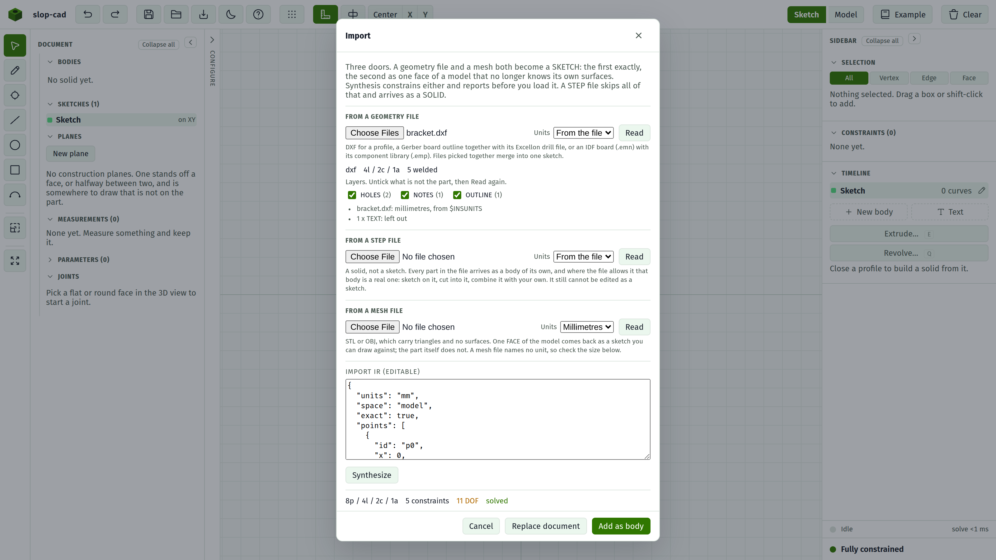
The import icon in the top bar opens Import. Its first section, From a geometry file, reads a file rather than a picture, so the numbers that arrive are the numbers somebody typed.
Four formats:
| Format | What it carries |
|---|---|
| DXF | A 2D profile. Lines, polylines with rounded corners, circles, arcs and points |
| Gerber (RS-274X) | A board outline layer |
| Excellon | A drill file: hole positions and sizes |
IDF (.emn + .emp) | A circuit board: outline, cutouts, drilled holes, and component outlines stood where the board places them |
A DXF
- Pick the file.
- Leave Units on From the file unless the file declares none, in which case its numbers are read as millimetres and the report says so.
- Press Read.
Reading and constraining happen together, so the report appears straight away. Then Add as body or Replace document, the same as any other import.
A board outline and its drills
Pick both files at once in the same file picker. An outline layer on its own is a shape with no holes in it, and a drill file on its own is a scatter of circles; read together they weld into a single sketch, which extrudes into a board blank.
The two files can be picked in either order, and the reader works out which is which from what is inside them, with the extension ignored.
An IDF board and its library
An IDF design is also a pair, split the other way: the board file (.emn) says where everything stands, and the library file (.emp) says what each component's outline is. Pick both at once for the populated board; pick the board alone for the blank, outline and holes, with a note counting the components that were left out. The library alone is refused, since it places nothing on its own.
The board's sections arrive as layer tickboxes, so a second read can keep exactly what the job needs: the outline for an enclosure, the outline with the drilled holes for a blank, or everything for a populated board to fit around. The board's own thickness is reported in the notes, ready for the extrude.
Keepouts and routing areas describe where the part may not go, so they are left out and counted. Components the board marks unplaced stay off the sketch.
What the report tells you
| Line | Meaning |
|---|---|
| The format names | Which reader handled each file |
| Nl / Nc / Na | Lines, circles and arcs read |
| N welded | Endpoints that turned out to be a corner already placed. A closed outline welds a lot; a count of zero on a shape that should be closed means the file has gaps |
| N driving | Dimensions the DXF stated that became driving constraints. See below |
| The unit sentences | What each file said its units were, one line per file |
| Notes | Anything assumed. Read these |
| left out | Content with no equivalent in a sketch, and how much of it |
| Layer tickboxes | Every layer the drawing put something on. See below |
What comes through, and what does not
A DXF gives up its lines, polylines, circles, arcs and points. A rounded polyline corner stays round: it arrives as an arc, not as the straight chord across it.
Blocks are stamped out where they are placed. A drawing that reuses one hole, one fastener or one bracket stores the shape once and places it many times, with its own offset, size, rotation and array counts each time. All of that is followed, and a block placed inside another block is followed too. This is what a drawing built from blocks needs to arrive as anything at all.
Splines arrive as straight segments through the curve. There is no spline in the sketcher, so this is the one thing here that is approximated, and the report says how many were read that way. The shape is right to the eye and the curve itself is gone: what you can dimension afterwards is the segments.
Text, hatching and ellipses are left out and counted in the report.
A Gerber is read along the centre line of its traces. On an outline layer that is exactly right, since the aperture there describes the router bit rather than the edge of the board. Feeding in a copper layer instead gives you the middle of every track, which is geometry but not a shape.
Excellon slots are left out, with a note. A slot is a path, and the reader only makes holes.
Reading one layer of a busy drawing
A drawing is usually more than the part. A sheet border, a title block, centre lines and hatching are all geometry, and nothing in the file marks which of it is the shape you came for; the only thing that separates them is the layer each sits on.
So the report lists every layer, with how many entities it holds. Untick the ones that are not the part and press Read again.
Reading twice is the way round this, and it costs nothing: what a drawing holds is not knowable until it has been read once.
An entity inside a block that says layer 0 counts as being on whatever layer the block was placed on, which is the DXF rule and means a layer means the same thing whether or not the geometry came through a block.
Dimensions the file already carries
A DXF is exact and arrives with hundreds of degrees of freedom, and the numbers the designer typed are sitting in the file. Every dimension whose definition points name geometry the reader placed becomes a driving constraint: linear and aligned ones as a distance, radial and diametral ones on the circle or filleted corner they point at, and angular ones between two lines.
Those numbers are then editable, and the drawing follows: change the width the file states and the part is that wide.
A dimension whose points name nothing in the drawing is reported and left out instead of aimed at the nearest thing. A constraint on the wrong pair of corners is worse than a missing one, because the sketch still solves and the part is quietly the wrong shape.
Ordinate dimensions have no constraint to become, and are counted.
After reading
An imported file arrives under-constrained on purpose, and the report will say so. Nothing is inferred from it except which edges were meant to be truly horizontal or vertical, and one anchor point so the sketch is not free-floating. Everything else is left as it is, because a file is not a guess: two holes whose sizes differ by a hundredth differ by a hundredth, and inventing an Equal between them would be a change rather than a reading.
Dimension it as you would any sketch. Adding your own driving dimensions is what turns the import into something parametric.
When the size looks wrong
Two files can be ambiguous about scale, and both say so in the notes.
A DXF that declares no units is read as millimetres. If it was drawn in inches, set Units to Inches and read it again.
A drill file that writes no decimal points and does not say which zeros it dropped is read one particular way, and the note names it. If the holes come out ten times too far apart, the file meant the other one; the fix is to re-export the drill file with decimal points, which every modern toolchain can do.
See also
- The import dialog, for every control
- Import a mesh, for the other door into a sketch
- Extrude, for turning the profile into a solid