
Appearance
Model view
The 3D half. Reached with the Model button in the top bar, which stays disabled until a solid exists and reads Extrude a profile first until then.
You also land here automatically when you create an extrude, and when you press the eye icon on a timeline row.
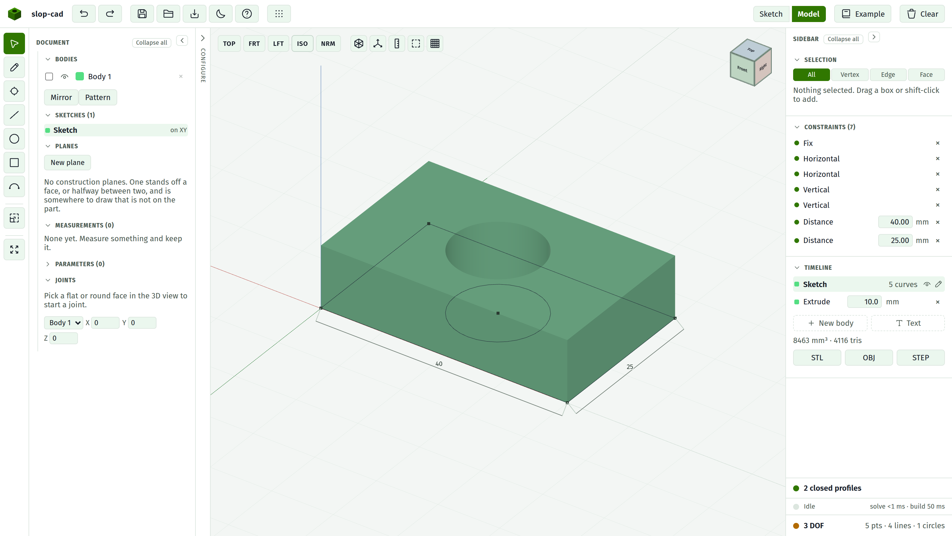
With no solid the canvas reads No solid yet. Extrude a profile., or building solid… while one is on its way.
Navigation
| Gesture | Action |
|---|---|
| Left drag | Orbit |
| Scroll | Zoom |
| Right drag | Pan |
Motion stops the instant the drag does; there is no glide.
The camera frames the model once, when the view first opens. Later rebuilds leave your camera where you put it, so editing a dimension does not yank the view around.
A hint strip states these bindings the first time you enter the view. Dismissing it is remembered.
Arriving in the model view leaves the Select tool active, so a click picks rather than draws.
The navigation cube
A small cube in the top right corner.
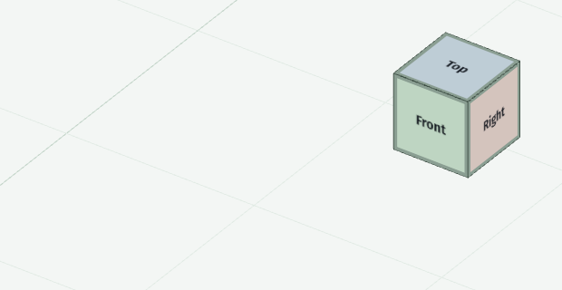
Its faces are labelled Top, Front, Right and so on, and it is not a picture: it turns as you orbit, mirroring where the camera is. So it doubles as an orientation readout, and whichever of its faces points at you is the face of the model you are looking at.
Clicking it aims the camera:
| Click | Result |
|---|---|
| A face | Look straight down that axis |
| An edge | Look down the 45 degrees between the two faces meeting there |
| A corner | An isometric view down all three |
That gives twenty-six directions against the view buttons' four, which is the point of it.
The face under the cursor brightens, so you can see what a click will take before you take it. Each face is tinted by the axis it faces along, in the same red, green and blue the axes in the viewport use, so which way the cube is turned reads before any label does.
Dragging over the cube orbits the model, exactly as dragging anywhere else does. Only a click without a drag aims the camera.
Looking straight down the up axis leaves the camera's roll undefined, so the top and bottom views lean a hair off exact, exactly as the TOP button does.
View buttons

One row along the top left of the canvas. The four views are words and the tools are marks, which is the difference between them: a view is something you ask for by name, a toggle is a state you read at a glance.
| Button | Result |
|---|---|
| TOP | Look straight down. Also Alt+T |
| FRT | Look along the Y axis, at the front. Also Alt+F |
| LFT | Look along the X axis, at the left side. Also Alt+L |
| ISO | The standard three-quarter view. Also Alt+I |
| NRM | Look square at the active sketch's plane, or at the construction plane most facing you when no sketch is open. Also Alt+N |
| X-ray | Toggle. See below |
| Axes | Toggle the move arrows. Also G |
| Ruler | Toggle the measuring tool. Also M |
| Dashed square | Toggle the projector |
| Orthographic / Perspective | Toggle. See below |
Each of the named views frames the model at three times its bounding radius along that direction.
The first four name absolute directions, which stops being the question once a sketch sits on a face or a construction plane. NRM answers the other one: look square at the thing you are working on. It keeps to the side of the plane you are already on, so it never swings the camera through the part, and it only appears when there is a plane to face.
Orthographic and perspective
The model view is orthographic by default: parallel lines stay parallel, and a feature projects at the same size and place whatever its depth. It is why a sketch overlay sits on the feature it belongs to, and why TOP, FRT and LFT are worth having at all.
Perspective is the other setting, and it is the one you get with a real camera: nearer things project larger and displace outward from the centre of the view. It reads more naturally for looking at a finished part, but a sketch drawn on a boss's base will appear offset from the boss, by more the further the boss sits from the middle of the view. That is the projection, not a modelling error.
The toggle is the last button in the row, and its icon shows which projection you are in. Switching keeps the camera where it is. Unlike X-ray, the choice is remembered between sessions.
X-ray
Makes the solid translucent so the sketch on a face, and the geometry behind it, stay visible while you work.
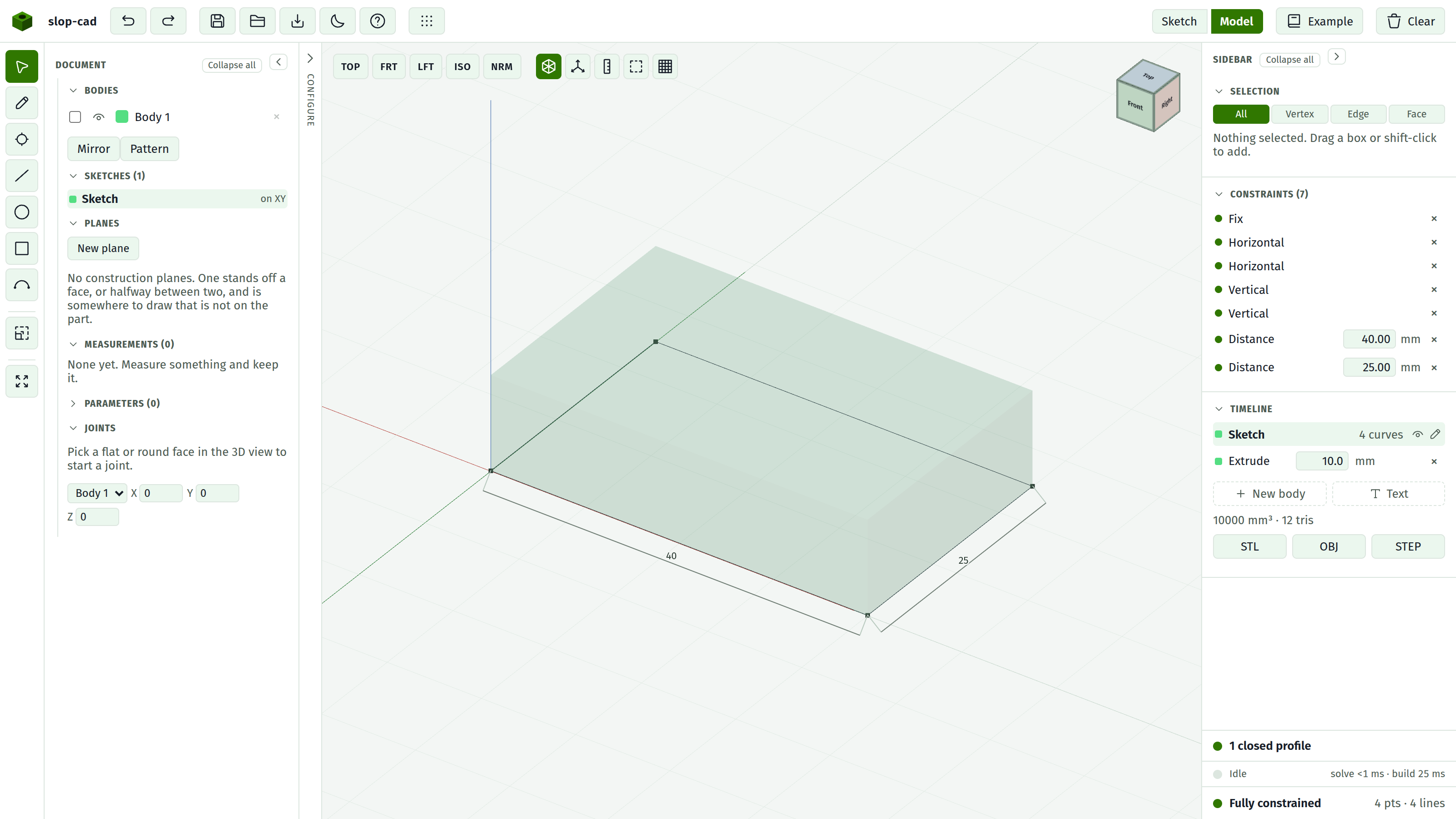
It is a toggle, it survives a rebuild, and it is not remembered between sessions.
There is a second, different X-ray in the sketch view, which underlays the parent sketch on the current plane. See sketching in 3D.
The axes
Red for X, green for Y, blue for Z, scaled to the model, and the same three colours the navigation cube tints its faces with. Z is up. X and Y run both ways through the origin; Z only rises, since there is nothing to measure below the floor. A 400 mm ground grid sits under everything for a sense of scale.
Picking
A click that does not move more than a few pixels is a pick rather than an orbit, so you can drag freely without selecting things by accident.
What gets picked depends on the select mode:
| Mode | Picks |
|---|---|
| All | An edge if the cursor is within 7 px of one, otherwise the face |
| Vertex | Corners of the body, and sketch points on the active plane |
| Edge | Edges only |
| Face | Faces only |
Sketch points never take a tap away from the face beneath them except in Vertex mode. They can still be dragged in any mode.
A picked face draws as an amber overlay. A picked edge draws as a thick amber line that shows through the solid.
Edges on the far side of a silhouette are not grabbable through the body, so clicking near an outline picks the edge you can see.
The Selection section reports what you picked and offers what applies: Sketch on face for a flat face, blends for a face or an edge, coordinates for a corner.
Clicking empty space clears the pick. So does switching to the sketch view, or removing the feature that owned it.
Moving a body
While the move tool is armed, a pick chooses the body the face belongs to and stands three arrows at its centre. Dragging one slides the body along that axis; the orbit lets go while a handle is held. Grid snap rounds the drag to the millimetre.
The Selection section says which body the arrows are on and where it stands, and a second pick on another body offers to land the first face flush on the second.
A body a joint holds gets no arrows: its joint decides where it stands, and the panel says which body to move instead.
Measuring
While the measuring tool is armed, a pick feeds the measurement instead: the Selection section reports the reading rather than the things a pick usually offers, and the sketch overlay stops taking clicks so a corner is reachable. The reading is also drawn over the model, across the span it was taken.
A reading can be kept, which leaves it drawn on the model and re-takes it off every later solid. See measuring in 3D.
Tracing into the sketch
While the projector is armed, a pick brings that thing into the active sketch as locked reference geometry instead of selecting it: a corner as a point, an edge as a line, a flat face as its whole outline, a hole as a circle. The Selection panel lists what the sketch has traced, and each one is re-read off every later solid.
Sketching in here
You can draw with the Pencil directly onto the active sketch plane, and drag with Select.
Pressing on a sketch point drags that point. Pressing anywhere else along a line, circle or arc grabs the whole entity, and the drag slides it without changing its shape. Points win where the two overlap, so a press on an endpoint still means that endpoint.
A tap goes to the face under a point rather than to the point; switch to Vertex mode to select the point itself.
A text feature is dragged whole: press anywhere on the letters and the block follows the cursor across its plane.
The sketch is drawn where the body stands, so a sketch on a moved body's face sits on that face rather than back where its features built it.
The sketch's dimensions draw on its plane here, turning with the model. They are for reading only in this view: placing one, or editing its value, is done in the sketch view where you can aim at it without fighting the orbit.
See sketching in 3D.